![20190507 Blog post 1600x900 Design Considerations[4]](https://blog.deregtcables.com/hs-fs/hubfs/20190507%20Blog%20post%201600x900%20Design%20Considerations%5B4%5D.jpg?width=708&name=20190507%20Blog%20post%201600x900%20Design%20Considerations%5B4%5D.jpg)
Every ROV project has its own system requirements. For a fit-for-purpose cable design, these system requirements have to be translated into cable requirements. In other words, the link between system requirements, cable requirements and cable design is crucial for a successful subsea project.
In this blog, we take a look at the system requirements with the greatest impact on cable requirements and the cable design. Read more in this free to download whitepaper.
The system requirements with the greatest impact on the cable design and requirements
Figure 1 shows a generic cable design for a dynamic cable (this cable was used for a wave energy system): components are layed up in helices, with extruded plastic sheaths and tapes to separate the layers. The electrical and optical components are layed up in the core. A steel strength member is then wrapped around the core, which we call a steel armour.
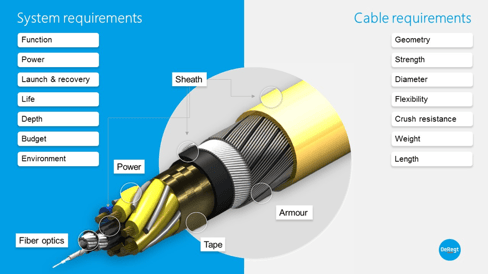 Figure 1: the system requirements that have the greatest impact on the cable design and the cable requirements that are influenced by these system requirements
Electrical conductors are usually made of copper with a thermoplastic insulation, while data is usually sent via optical fibres. The helical construction allows the cable to be bent and stretched, without damaging any components. We design cables in such a way that the load is transferred through the strength member, and not through the electrical and optical components.
Let's take a look at these system requirements.
1. Function
Common functions of the cable are: supplying power, sending control instructions or receiving signals and data. These functions define the type, size and number of components and how they are integrated. In other words: the geometry.
If the function is also to support towing, deployment and/or recovery loads, it will directly impact the required strength. To define the required strength you have to define the load. It is important to analyse the applied loads for every scenario and to define the Dynamic Amplification Factors, hoisting motion factors and duty factors.
Another function of the cable could be to reach or maintain a certain depth (while being towed behind a vessel). In this case, weight is another cable requirement that is related to its function.
2. Power
Power is a big driver for the diameter, weight and geometry of the cable. It has a direct impact on the size of the conductor and thickness of the insulation. The size of the conductor is either determined by current or by voltage drop. With current, heat is the limiting factor. In the water it will not have any issues. However, if it is deployed in shallow waters, with many layers on the winch, it could cause problems.
The maximum voltage drop can also be the driving factor for the size of the conductors. For the electrical circuit of the system it could become critical if the voltage drop in the cable is too high.
Electrical stress is another important consideration. We design cables to keep the voltage stress below 2.5kV/mm. Otherwise air can ionize and generate discharges. This will eventually burn up your plastic insulation. Voltage stress decreases along with radius. Making the insulation thicker helps.
3. Launch & recovery
The launch & recovery method usually has a major impact on the cable design. The diameter of the cable influences the minimum bend radius. This directly affects the size of the winch and handling system.
Flexibility impacts the ease of handling. A cable can be made more flexible by increasing the helix angle. When we increase the helix length the cable will become stronger in tension, but less flexible (and vice versa). It is important to find a good balance between these two.
During the deployment and recovery cycle, the cable is often subjected to multiple bend cycles, which is why we have to mention fatigue here as well. Fatigue life is related to the strength and flexibility.
As the cable will frequently pass fairleads and sheave wheels, or will be clamped onto another structure, it is important to consider the crush resistance. A cable with a steel strength member has far greater crush resistance than a cable with an aramid or other synthetic fibre strength member. Most dynamic cables need to support their own weight as well. In those cases, self-weight and strength are key drivers for the design.
4. Life
Of course the required cable life plays an important part in the design process. DeRegt designs cables in such a way that the strength member fails first. The fatigue life is what we consider here. One way of looking at fatigue life is the life factor. The life factor is the safety factor on a load multiplied by the D over d ratio (the diameter of the sheave wheel divided by the diameter of the cable).
It’s not only about the number of deployment and retrieval cycles when considering fatigue. The cable is also subjected to many fatigue cycles while being towed behind the vessel. Normally the cable passes a sheave wheel at the back of the vessel. The vessel will move up and down due to wave motion, causing the cable to bend an enormous number of times.
Verification of the cable life by performing qualification testing is a must for dynamic cables. The most important test is the Bend over sheave fatigue test, because almost all cables fail due to repeated bending.
5. Depth
The operating depth is an important factor, as the required length and diameter are directly related to the operating depth. 6,000m depth requires a very different cable than 500m depth. For example, the diameter changes because the size of the conductors and required length determine the voltage drop.
Another crucial point is void filling: 6,000m depth requires the cable to be completely air void free. Every air void would otherwise collapse and might cause the cable to fail.
6. Budget Figure 2: cable constructions
 A large proportion of the cable costs is a result of the number of lay-up operations required.
In the top picture in Figure 2 all components are twisted up at the same time. We call that uni-lay.
Because everything is twisted together in one go, the production cost is lower. It’s often the most compact construction as well. Each component has the same lay length and therefore different helix angles. This is a disadvantage. Components in the centre have a small helix angle which means that when the cable is loaded, the conductors will stretch the most which could lead to the possibility of the copper failing. Another disadvantage of uni-lay is back twisting. The amount of back twist is related to the helix angle, so with different helix angles we need different back twisting compensation.
When we look at the picture in the middle we see a concentric lay-up. This means the cable has to go through the machine twice. Making it more expensive. Advantage is that the components in each layer have the same helix angle and therefore the same back twist requirements.
The bottom picture shows a group-lay construction. In this case the cable is constructed using 4 different lay-up processes. It’s the most flexible construction, but also the most expensive.
7. Environment
The last system requirement to mention is the environment. Marine Cables can be used in almost all marine environments. DeRegt always uses corrosion resistant materials and they are not affected by most environmental requirements. The strength member is normally made of corrosion resistant galvanised steel. If corrosion is a very significant issue (due to use in very warm waters for example) we sometimes use Nitronic 50 stainless steel as a strength member.
Requirements with regards to chemical resistance do not have a significant impact on the design either, since the materials selected by default already have compatibility with the chemicals listed in the system requirements for most systems used in a marine environment. Shock and vibration are also not a driver for the cable design. Operating and storage temperatures hardly ever exceed the maximum allowable temperatures for the default materials used in cables.
So, in general, most marine-environment requirements are not a big driver for the cable design at DeRegt. However, for extreme situations (in oil-wells for example) the design is impacted significantly by the environmental requirements. It is therefore always recommended that you specify the environmental requirements in detail.
What do these requirements mean for your specific ROV project?
To enable you to write down your cable requirements as detailed as possible, our specialists wrote a white paper. Download it here for free.

More information about crucial design considerations: